
From sculpture to recipe: reconstructing CAD from meshes
A mesh is a sand sculpture: a million grains, looks right, can't be edited.
CAD is the recipe, with named dimensions.
Scanners and 3D generation keep making better sculptures.
We write the recipe from the sculpture, and grade every attempt against it.
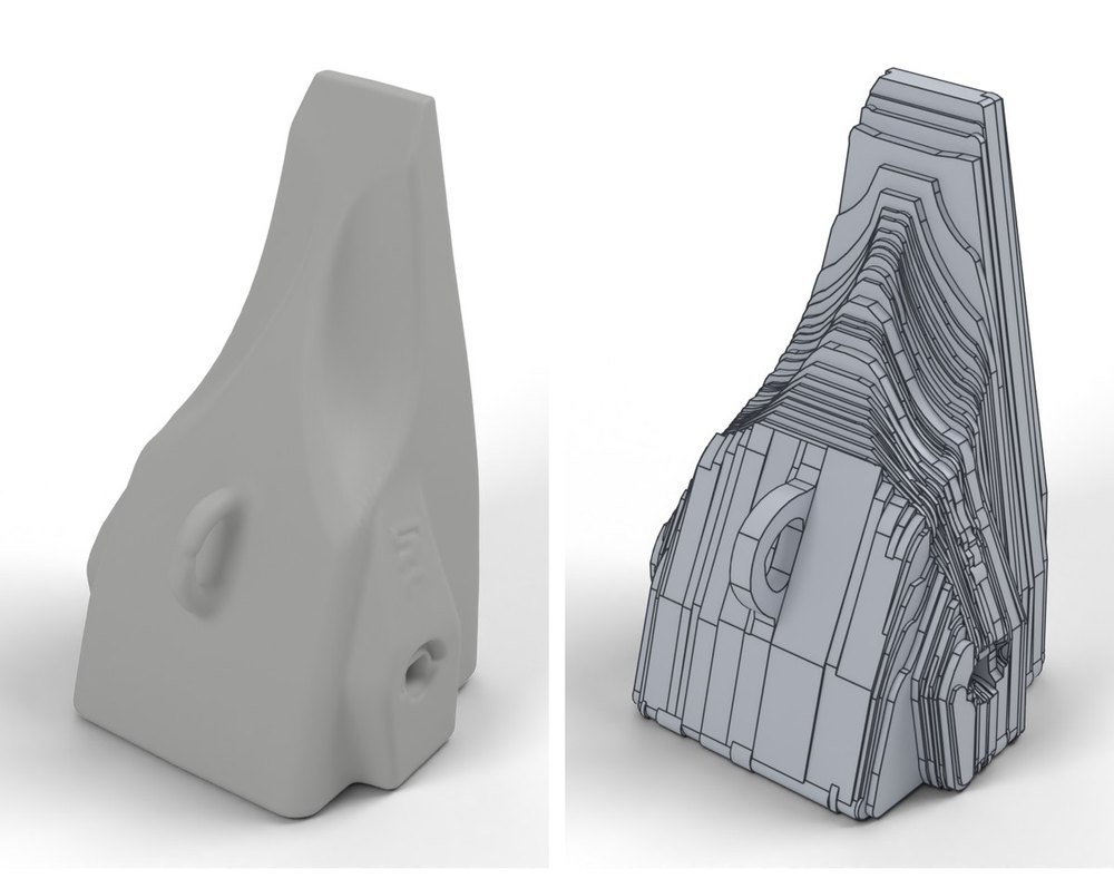
A mesh can be reshaped, but not edited parametrically: it has no features or dimensions to change. Turning one into CAD still means an expert rebuilding it by hand. Mesh-to-CAD reconstruction recovers that model: one that builds, matches the shape, and is clean enough to edit.
- A mesh shows the shape; engineering runs on CAD. Reconstructing CAD from 3D geometry is well studied on clean data, but scores roughly halve on real parts.
- We built two stages. A construction pipeline builds a valid base model and measures the part. An LLM then writes a new parametric program from those measurements, inside a harness that checks every attempt against the mesh.
- Stage 1 gets most parts to a valid model. We ran it on 60 meshes of mechanical parts: 44 of 60 became a single solid that survives export to STEP.
- Stage 2 makes it closer and cleaner. In a four-part pilot it cut missing geometry by up to 4.5× and the face count by up to 8×, and produced a valid engine block where stage 1's attempt broke on export.
- Published methods, tried on the same meshes, missed 17–87% of the geometry, against 1.8–7.1% for our full method.
1Reconstructing CAD from 3D
There are two ways to arrive at a CAD model with AI: reconstruct it from 3D geometry, such as a scan, a point cloud or a mesh, or generate it from images, drawings or a description.
Work on reconstruction falls into five families.
| Family | How it works | Examples |
|---|---|---|
| Fit primitives | Fit surfaces, then join them | Point2CAD1 |
| Recover the B-rep | Predict faces, edges and corners together | ComplexGen2, DualBrep3 |
| Recover the build steps | Predict sketches, extrusions or CAD code | DeepCAD4, CAD-Recode5, cadrille6 |
| Search and build | Try build operations, keep what matches | CADFit7 |
| Agents in a loop | Write CAD, run it, compare, try again | Published agentic approaches8 |
Most of this work is trained and tested on shapes sampled from clean CAD. Real and noisy inputs are where it gets hard.
2What we built: two stages
We built a two-stage reconstruction for meshes, combining two of the families above. A construction pipeline first searches for a way to build the part, produces a valid base model and measures the part. A large language model (LLM) then writes a new parametric CAD program, guided by the pipeline's measurements and the harness's error feedback. The harness builds, checks and scores every attempt, and the LLM repairs its program until the result stops improving. It does not edit the pipeline's model; it rebuilds the part as a cleaner program.
Input mesh
Detailed shape, no CAD structure.
Stage 1 · Pipeline
Chooses how to construct the part, builds a valid base model and measures the part.
Stage 2 · Refinement loop
The LLM writes and repairs a new parametric program; the harness builds it into a solid.
Check
Does it build? Does it match the mesh, and where not? Is it clean?
Output
The best valid attempt: a program with named dimensions, and its STEP file.
3How we score a result
A single similarity score can rate a broken part highly. We ask three separate questions of every result.
The measuring stick needs checking too. Scoring large flat faces without subdividing them first reported 28% error on a part whose true figure was 13%.
There is a fourth question we cannot answer yet: is it the right part? Every score here is measured against the mesh, and the mesh is itself only an approximation of the part. Section 5, What's next, comes back to it.
4Results
One part, step by step
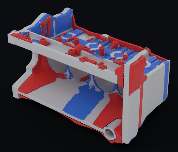
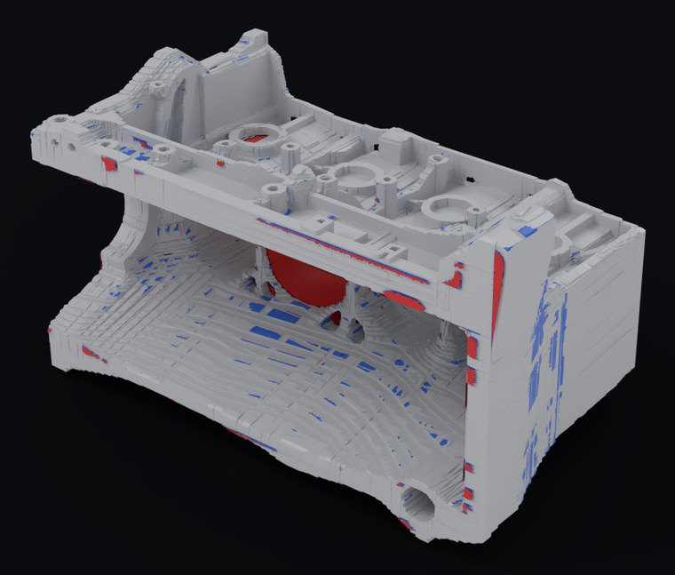
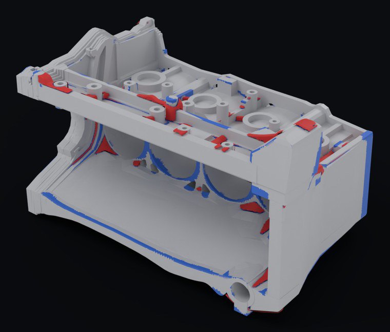
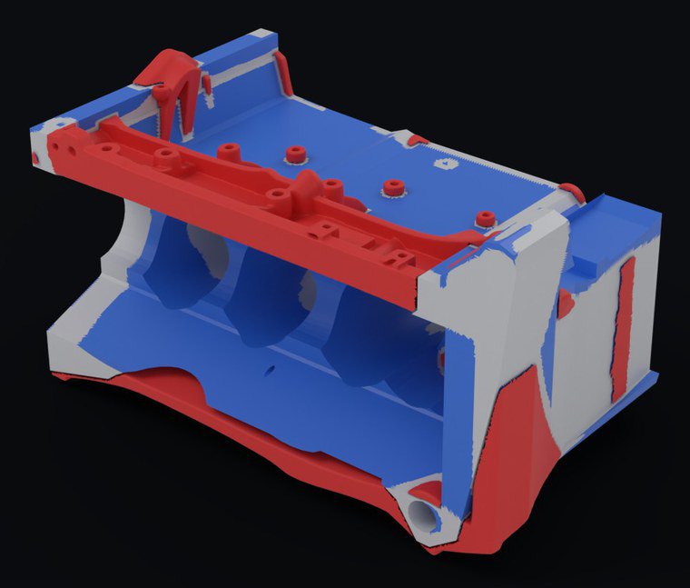
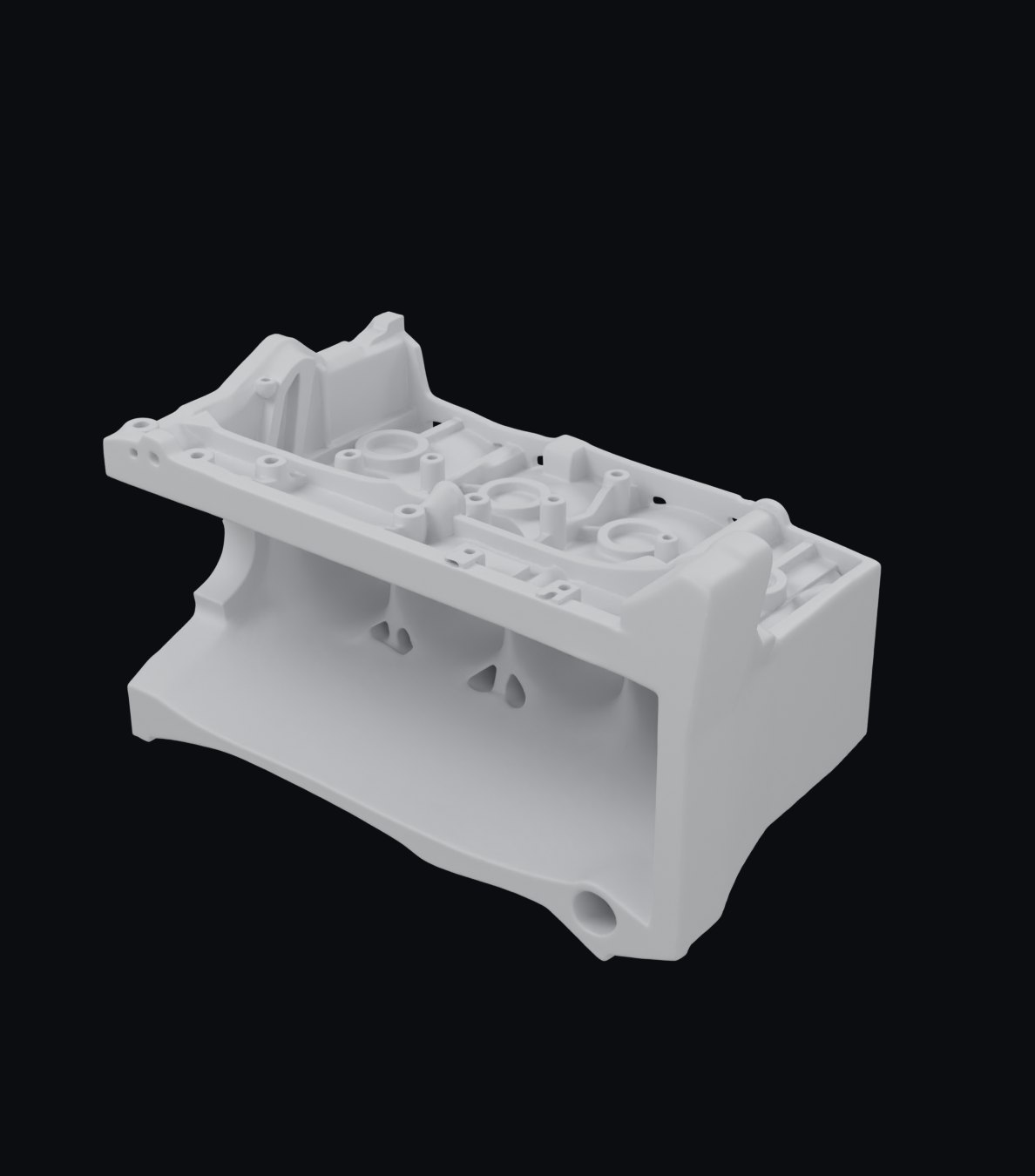
The engine block at the top of this article is a mesh of about a million triangles: four cylinder bores, a hollow crankcase, ribs and bosses. Each picture there is the CAD from one step, compared with the mesh: grey where it matches, red where it misses part of the mesh, and blue where it adds geometry the mesh doesn't have. A surface counts as missed or added when it is more than 2 units from the other (0.35% of the part's size), the same cut-off as the scores, so the red and blue areas are the missing and extra shares.
- 01One pass. The LLM's first program, before the harness has fed anything back, misses 43.1% of the mesh and adds 35.1% that is not there. It is a valid solid, but not this part.
- 02Stage 1. The pipeline got close to the mesh: 10.6% missing and 5.5% extra. But its best attempt was 40,974 stair-stepped faces with one cylinder bore filled in solid, and it broke once written to STEP. No pipeline method produced a valid solid for this part.
- 03Stage 2. Over 19 iterations and 76 minutes, the LLM in the harness produced one valid solid: 7.1% missing, 7.5% extra, and 2,803 faces, about 15× fewer than the stage 1 attempt. The error that remains sits at a few edges and bore rims.
Stage 1 across 60 meshes
We ran the pipeline on 60 meshes of mechanical parts: brackets, housings, turned parts, gears, valve blocks and castings, from about 90,000 to a million triangles each.
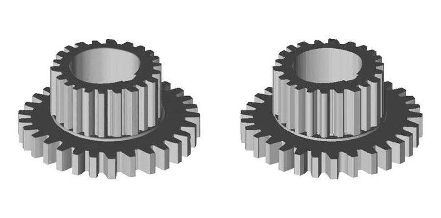
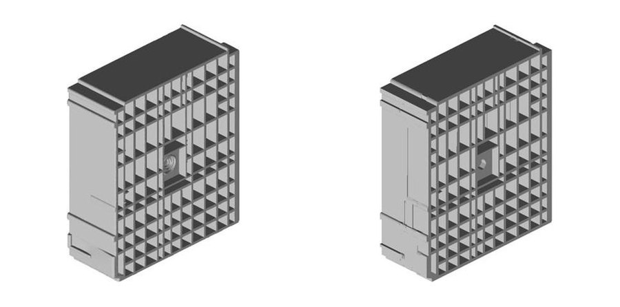
- Does it build? 44 of 60 parts become a single solid that survives a round trip through STEP. Large castings are the hard case: three of them never became a valid solid, whatever we tried.
- Does it match? 34 of 60 are also within the bar: at most 10% of the mesh lies more than 0.35% of the part's size from the CAD, and at most 15% of the CAD lies that far from the mesh. Gear-type parts come back within 0.3% both ways. Picking the best construction per part after scoring raises the count to 42 of 60. That is an upper bound, because the same score makes the choice.
- Is it clean? Valid results have a median of about 1,250 faces. Some passing results are visibly stair-stepped, which is why we look at every one.
Stage 2 on four parts
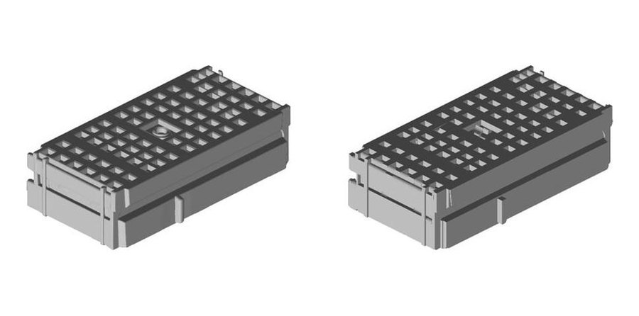
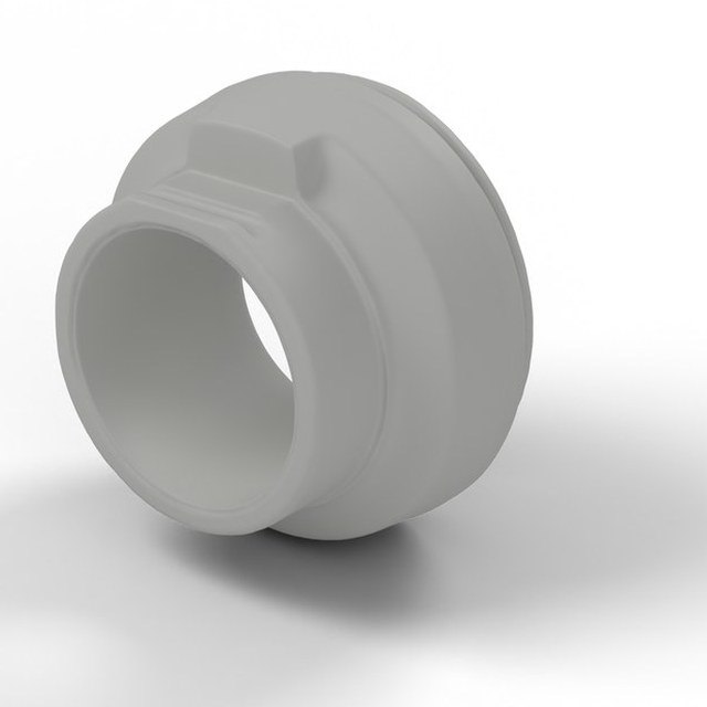
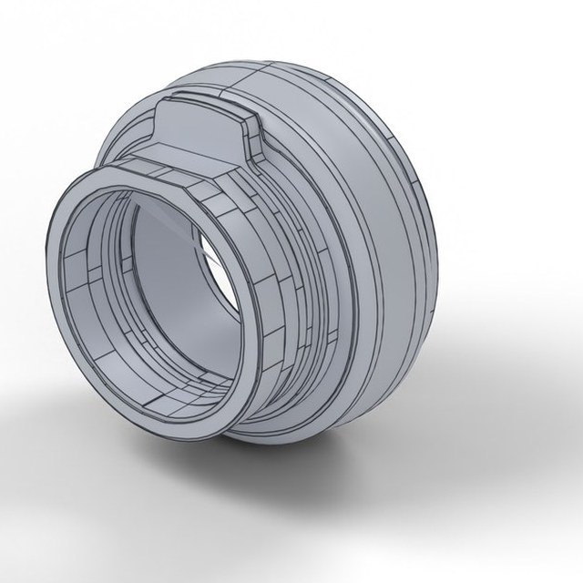
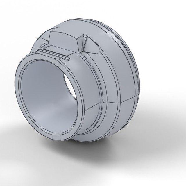
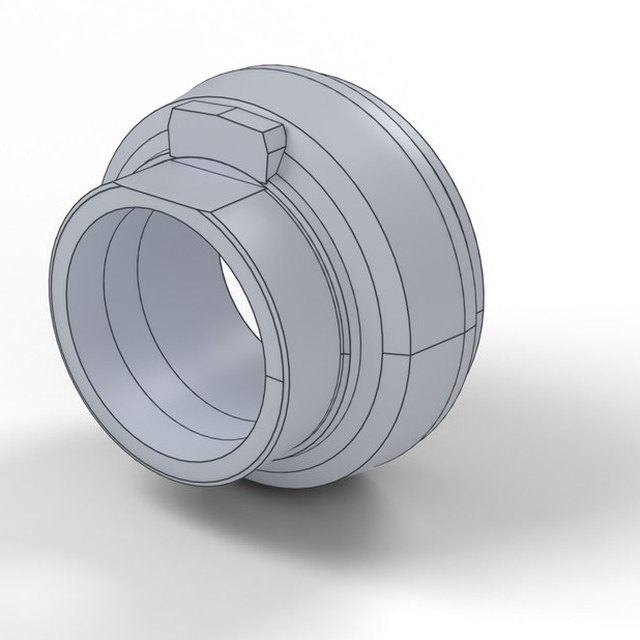
We then ran the second stage on four parts: a hub, a bearing, a valve block and the engine block above.
Published methods on the same meshes
To see how published approaches handle these meshes, we ran three of them on the same four parts and scored every result with the same tool: CADFather8, cadrille6 and CAD-Recode5. In CADFather, a vision-language model picks the tools that build the geometry; in our stage 2, the LLM writes the parametric program itself.
| Method | Input → output | How it was run | Parts |
|---|---|---|---|
| Stage 1 + stage 2 | mesh → measurements → parametric program → solid | Our full method. Stage 1 builds a base model and measures the part; stage 2, an LLM in our harness, writes and repairs a new parametric program. Best valid attempt of 12–19, chosen by the score shown here. | All four parts |
| Stage 1 only | mesh → solid | Our construction pipeline on its own: the best valid method per part (for the engine block, its best attempt, which is not a valid solid). | All four parts |
| CADFather | mesh → CAD program → solid | Open-source code, full system. A vision-language model picks the tools that build the geometry. One run per part, with a commercial assistant model in place of the paper's. | All four parts |
| cadrille | 256 points → CAD program → solid | The authors' released model and preprocessing: 256 points sampled from the mesh. Best of 10 samplings, chosen by our score; all 10 programs ran on every part. | All four parts |
| CAD-Recode | 256 points → CAD program → solid | The authors' released model (v1.5), same setup as cadrille. Best of 10 samplings; 5, 10, 10 and 7 of the 10 programs ran on the valve block, hub, bearing and engine block (the rest fail in CAD code). | All four parts |
| Method | Hub | Bearing | Valve block | Engine block |
|---|---|---|---|---|
| Stage 1 + stage 2 | 1.8 / 2.2 70 faces | 6.2 / 2.7 180 faces | 4.6 / 6.1 345 faces | 7.1 / 7.5 2,803 faces |
| Stage 1 only | 8.2 / 12.3 545 faces | 19.6 / 13.7 463 faces | 5.4 / 10.8 1,598 faces | 10.6 / 5.5 40,974 faces · not valid |
| CADFather8 | 17.2 / 18.2 37 faces | 57.5 / 53.1 46 faces | 39.3 / 35.6 59 faces | 71.3 / 61.3 142 faces |
| cadrille6 | 58.3 / 58.0 16 faces | 71.4 / 61.6 6 faces | 54.6 / 52.2 25 faces | 86.2 / 74.0 34 faces |
| CAD-Recode5 | 65.7 / 63.8 11 faces | 61.7 / 56.8 36 faces | 65.8 / 58.1 32 faces | 87.3 / 78.8 41 faces |
Each cell: missing % / extra %, then the face count. cadrille and CAD-Recode were designed for clean point clouds sampled from CAD, and see only 256 points of these meshes, so their numbers show the gap on this kind of input rather than a flaw in the methods. CADFather's own metric is volume IoU; here it is also scored with ours.
5What's next
- Is it the right part? Today every score is measured against the mesh. Next we take parts whose real CAD we have, get meshes of them by scanning or generating, and compare each rebuild with the original on what an engineer checks: hole counts, key dimensions in millimetres, and handedness. That also tests whether a good score against the mesh really means a good part.
- A model trained for the loop. The strongest results so far come from a general-purpose LLM in the second stage. Next is a model trained for exactly this task, aiming for the same quality at a fraction of the time and cost per part.
- Editable, by test. Beyond a valid solid with named dimensions: change a dimension and check that the model rebuilds and stays valid.
- More kinds of mesh. Scans of physical parts and legacy files, which bring noise, holes and missing faces.
- The casting gap. Large organic castings are where every approach still struggles.
- Baselines beside every score, such as a bounding box or convex hull, so a number shows how much it really says.
References
- Y. Liu et al. Point2CAD: Reverse Engineering CAD Models from 3D Point Clouds. 2023. arXiv 2312.04962
- H. Guo et al. ComplexGen: CAD Reconstruction by B-Rep Chain Complex Generation. ACM Transactions on Graphics (SIGGRAPH 2022). arXiv 2205.14573
- Y. Liu et al. DualBrep: A Dual-Field Continuous Representation for B-rep Modelling. SIGGRAPH 2026. arXiv 2606.31579
- R. Wu et al. DeepCAD: A Deep Generative Network for Computer-Aided Design Models. ICCV 2021. arXiv 2105.09492
- D. Rukhovich et al. CAD-Recode: Reverse Engineering CAD Code from Point Clouds. 2024. arXiv 2412.14042
- M. Kolodiazhnyi et al. cadrille: Multimodal CAD Reconstruction with Reinforcement Learning. 2025. arXiv 2505.22914
- G. Nehme et al. CADFit: Precise Mesh-to-CAD Program Generation with Hybrid Optimization. 2026. arXiv 2605.01171
- G. Savrasov et al. CADFather: Autonomous CAD Reconstruction through Coordinated Tool Use. 2026. arXiv 2610.09127
- S. Kabisov et al. CADENA: Stepwise CAD Reverse Engineering. 2026. arXiv 2608.00799
- A. C. Doris et al. CadBench: A Multimodal Benchmark for AI-Assisted CAD Program Generation. 2026. arXiv 2605.10873
One result, in public.
Model drops, findings, and hands-on demos, published monthly, no gatekeeping. Bring your hardest part.